Front loading Fisher and Paykel washing machine error codes can be found here.
Check out this video how to retrieve the Fisher and Paykel washing machine fault codes on your washer with push button models.
Check out this video how to retrieve the Fisher and Paykel Aquasmart washing machine fault codes on your washer with sensor buttons.
Also we have a guide page on how to enter the service menu on Fisher and Paykel washing machine.
Fault 1 – Motor Controller Module Fault
Problem: The Motor Controller Module (Display for phase 1) has encountered an error.
Solution: Replace Motor Controller module.
Fault 2 – Pressure Sensor Fault
Problem: An error has been encountered when trying to read the pressure sensor.
Solution: Replace Motor Controller module.
Fault 3 – Motor Controller Module Fault
Problem: The Motor Controller Module has found a memory error.
Solution: Replace Motor Controller module.
Fault 4 – Communications Fault
Problem: The Display Module has had difficulty communicating with the Motor Controller.
Solution: 1. If still faulty Replace Motor Controller module.
2. Replace the Display Module.
Fault 5 – Communications Fault
Problem: The Motor Controller has had difficulty communicating with the Display Module.
Solution: 1. Replace the Display Module
2. If still faulty Replace Motor Controller module.
Fault 6 – Motor Controller Module Fault
Problem: The Motor Controller module has received an incorrect signal from the pressure sensor.
Solution: Replace Motor Controller module.
Fault 7 – Display Module Fault
Problem: The Display module has found a memory fault.
Solution: Replace Display module.
Fault 8 – Display Module Fault
Problem: The Display micro has not been able to start up correctly.
Solution: Turn off at the wall and on again after 5 seconds and try again.If still
faulty replace the Display Module.
Fault 9 – Machine Size Fault
Problem: The Display size switch setting does not match that stored in the memory.
Solution: Resize the capacity of the machine.
Fault 10 – Temperature Sensor Fault
Problem: The temperature sensor may be open circuit or the ambient temperature is below
minus 10oC.
Solution: 1. Check wiring to temperature sensor.
2. Replace Temperature sensor.
Fault 11 – Pressure Sensor Fault
Problem: While measuring the water level, the Motor Controller micro has detected a
negative pressure. Reconnecting the pressure tube to the pressure sensor while
the bowl has been partly filled with water may have caused this.
Solution: 1. Check bowl is fully pumped out. Remove pressure tube from pressure
sensor, clear pressure tube of any water and reconnect tube.
2. If fault is still present, replace the Motor Controller module.
Fault 12 – Overfill Fault
Problem: The Motor Controller module has found the water level to be above the flood level
and tried to pump the excess water out. (Under extremely high flow rate conditions
the machine may overfill during the “top-up” routine in agitate.) After pumping for
30 seconds, it has been unable to lower the water level below the flood level.
Either the water valves have stuck on and are letting water in at a flow rate that is
higher than the pump can handle, or the pump is blocked and can’t remove the
excess water.
Solution: 1. Check water valves to make sure they close when they should, replace valves if valves do not close when power is switched off while filling.
2. If valves are ok, replace Motor Controller Module
Fault 13 – Pump Fault
Problem: The Display module has detected that the pump is on when it should be off.
Solution: 1. Check wiring to drain pump, replace wiring or pump if open circuit.
2. Else, Replace the Display Module.
Fault 14 – Pump Connection Fault
Problem: The Display Module has detected that the pump is not on when it should be.
Solution: 1. Check wiring to drain pump, replace wiring or pump if open circuit.
2. Else, Replace the Display Module.
Fault 15 – Display Module Fault
Problem: The Display Module has read an incorrect voltage on the pump circuit.
Solution: 1. Replace Display module.
Fault 17 to 23 – Display / Motor Controller out of Sequence
Problem: The Display Module has read an incorrect voltage on the pump circuit.
Solution: Turn the Smartdrive off at the wall and then back on again in 5 seconds. Restart.
If the fault persists, disable auto restart feature and retest. A new fault code will
appear, carry out actions necessary to fix this new fault.
Fault 25 – Display Module Fault
Problem: The Intuitive Display has detected a problem with the LCD. Liquid Crystal Display.
Solution: 1. Replace Display module.
Fault 28 to 30 – Display / Motor Controller out of Sequence
Problem: Same as fault 17
Fault 32 – Pump Circuit Fault
Problem: The Display Module has detected that the pump is on when it is off.
Solution: 1. Check for moisture on control and display boards.
2. Replace display module.
Fault 33 – Water Valve Fault
Problem: The Module has detected a water valve fault.
Solution: 1. Check inlet valves are connected properly.
2. Check resistance on inlet valves.
3. Replace display module.
Fault 34 – Brake Resistor Fault
Problem: The circuit that controls the braking of the motor is faulty.
Solution: 1. Replace Motor controller.
Fault 35 – Display Module Fault
Problem: The Display Module has sent a false signal to the Motor Controller.
Solution: 1. Check wiring.
2. Replace Display Module.
Fault 36 – Water Loss Fault
Problem: The Motor Controller module has needed to top up the water level more than 4
times during agitation. This is excessive, as normally only one or two top ups are
required to replace the air that has escaped from a full load during agitation. The
most likely cause is that the machine is siphoning. The other alternative is that the
machine has developed a leak.
Solution: 1. Check that water is not siphoning water out of the machine.
2. Check pressure tube for holes and if connected firmly to drum and PCB.
3. Check for water leaks out of the drum.
Fisher and Paykel Washing Machine Fault 37 – Drain Pump Fault
Problem: This is one of the most common Fisher and Paykel washing machine fault codes. Fault 37 appears when the water has not drained from the drum.
Solution: 1. Check for blockages and foreign objects in drain pump.
2. Replace drain pump.
Fault 38 – Pressure Sensor Fault
Problem: The Motor Controller module has recorded a water level of empty while it is
agitating. The water level must have been greater than empty for the machine to
enter the agitate mode initially. The most likely cause of this fault is that the
pressure sensor hose has been severed or fallen off during agitation. Alternatively
the pressure sensor may be faulty.
Solution: 1. Check pressure tube for holes and if still connected to drum and PCB.
2. Replace Motor Controller.
Fault 39 – Temperature Tube Fault
Problem: The probable cause of this fault is that the pressure tube has become blocked or
kinked or has fallen off completely. Alternatively the pressure sensor may be
faulty.
Solution: 1. Check pressure tube for blockages and holes.
2. Replace Motor Controller.
Fault 40 – Bowl Dis-engage Fault
Problem: While carrying out a bowl check, the Motor Controller module has found that the
bowl is not engaged even though the pressure sensor indicates that the bowl is
empty. The Motor Controller module continues to check for 2 minutes, after which
time it displays this fault. The first two areas to check are the clutch and the
pressure tube. If these two appear correct, then the fault could be in the pressure
sensor in the Motor Controller module.
Solution: 1. Check that there are no foreign objects stuck in the clutch that are preventing the bowl to engage.
2. Check condition of clutch.
Fault 41 – Temperature Sensor Fault
Problem: The temperature sensor is measuring temperatures above 110oC. The fault is
probably due to a short circuit in the sensor line. (Only in the Intuitive Washer and
the GW Models.)
Solution: 1. Check for moisture on PCB boards.
2. Resistance of temperature sensor from PCB plug if ok, replace Motor Controller.
Fault 42 – Rotor Fault
Problem: The Motor Controller has had some confusing information
feedback.
Solution: 1. Unplug machine from power point for 10 sec.
Fault 43 – Out of Balance Switch Fault
Problem: The Motor Controller module has found that the signal returning from the out of
balance switch indicates that the switch is permanently on or the harness to it is
disconnected.
Solution: 1. Check condition of Out of Balance switch.
2. If switch ok, Replace Motor Controller.
Fault 44 – Water in drum during spin
Problem: The Motor Controller has sensed a water level in the bowl during spin. This may
be caused by a slow pump out rate due to a partial blockage in the pump hose or
pump.
Solution: 1. Check for blockages in draining system.
2. Check functionality of drain pump.
Fault 45 – Phase 5 Display Memory Check Fault
Problem: On power up, the display has checked its memory against a known reference and
found differences.
Solution: 1. Replace display module.
Fault 46 – Phase 5 IW – Display EEPROM Check
Problem: The Intuitive Display has detected a problem with its internal EEPROM.
Solution: 1. Replace display module.
Fault 47 – Phase 2 and 3 – Bowl Dis-engage Fault
Problem: While carrying out a bowl check, the Motor Controller module has found that the
bowl is not engaged even though the pressure sensor indicates that the bowl is
empty. The Motor Controller module continues to check for 2 minutes. During this
time the module has not been able to determine a valid bowl status and so
displays this fault. This fault differs from fault 40 in that a valid bowl status could
not be determined. The first two areas to check are the clutch and the pressure
tube. If these two appear correct, then the fault could be with the pressure sensor
in the Motor Controller module.
Solution: 1. Check that there are no clothes or other foreign objects preventing the
clutch from re-engaging.
2. check that the pressure tube has not come off and that it is not kinked.
3. Replace Motor Control Module.
Fault 48 – Hot and Cold Valve Faulty
Problem: Motor Controller detected that the inlet valves are faulty.
Solution: 1. Check resistance of valves from PCB plug.
2. If valve resistance values in range, replace motor controller.
Fisher and Paykel Washing Machine Fault 49 – Cold Valve Faulty
Problem: Fault 49 is another Fisher and Paykel washing machine fault codes that appears frequently. Motor Controller detected that the cold inlet valve is faulty.
Solution: 1. Check resistance of valve from PCB plug.
2. If valve resistance values in range, replace motor controller.
Fisher and Paykel Washing Machine Fault 50 – Hot Valve Faulty
Problem: Motor Controller detected that the hot inlet valve is faulty.
Solution: 1. Check resistance of valve from PCB plug.
2. If valve resistance values in range, replace motor controller.
Fault 51 – Diverter Valve Fault
Problem: The motor controller has registered a drop in water level in the
recirculation phase of the wash cycle, water is being drained instead of
recirculated. Or water has been sprayed onto the Valve from an external source
and caused the solenoid to blow.
Solution: 1. Check for blockages in diverter valve.
2. Check resistance of diverter valve, should be between 0.7kΩ and 2.5kΩ.
Fault 52 – Diverter Top-up Fault
Problem: More than 6 attempts to top-up the water level in the bowl, this then signifies the
valve has not closed and is diverting to drain, or the top-up was not increasing
quick enough suggesting the valve has a blockage and is also draining.
Solution: 1. Check for blockages in diverter valve.
2. Check resistance of diverter valve, should be between 0.7kΩ and 2.5kΩ.
Fault 53 – Rotor Position Sensor Step Fail
Problem: The motor controller has attempted a motor step test and has found that the motor
has not stepped in the correct direction. It has detected that the motor is
connected and that the motor drive is operational. The rotor position sensing
system is at fault here.
Solution: 1. Check wiring from PCB to Rotor position sensor.
2. Replace rotor position sensor.
3. Replace Main PCB.
Fault 54 – Motor/Motor Controller module Step Fail
Problem: The Motor Controller module has attempted a motor step test and has found that
the motor has not stepped in the correct position. The Motor Controller module has
detected that there is no current. This indicates that either the motor is not
connected or the Motor Controller module motor drive is faulty.
Solution: 1. Check wiring from PCB to motor.
2. Check motor windings.
3. Replace Main PCB.
Fault 55 – System Step Fail
Problem: Rotor Position Sensor is faulty.
Solution: 1. Check wiring from PCB to motor position sensor.
2. Replace motor position sensor.
3. If still faulty, Replace Main PCB.
Fault 56 – Bowl Check No Valid Fault
Problem: While carrying out a bowl check, the machine has not been able to determine a
valid bowl status and so the Display flags this fault. This fault differs from fault 40
in that a valid bowl status could not be determined. The first two areas to check
are the clutch and pressure tube. If these two appear correct, then the fault could
be with the pressure transducer in the motor controller.
Solution: 1. Check that there are no clothes or other foreign objects preventing the
clutch from re-engaging.
2. Next check that the pressure tube has not come off and that it is not kinked.
Fault 57 – Brown Out During Display EEPROM Write Fault
Problem: The Display has requested the Motor Controller module to perform an EEPROM
write. Prior to writing, the Motor Controller has tested the 15 Volt supply and found
that it is below the safety level for writing EEPROM and has reported this to the
Display. This may be due to transients at the time of writing or due to a faulty
Motor Controller module.
Solution: 1. Replace Motor Controller module.
Fault 58 – Pressure Transducer at Maximum Adjustment Fault
Problem: When the pause or delay start is pressed to start the machine, the Display has
checked the memory and found the count greater than expected.
Solution: 1. Replace Motor Controller module.
Fault 59 – I D Out of Range Fault
Problem: When the pause or delay start is pressed to start the machine, the Display
checked the physical ID and found it was out of range.
Solution: 1. Replace Display module
Fault 60 – Motor Control Memory Check Fault
Problem: On power up, the Motor Controller module has checked its memory against a
known reference and found differences.
Solution: 1. Replace Motor Control module
Fault 61 – Brown Out During Motor Controller EEPROM Write Fault
Problem: The Motor Controller module has been attempting to perform an internal EEPROM
write. Prior to writing, the Motor Controller has tested the 15 volt supply and found
that it is below the safety level for writing EEPROM and has reported this to the
display.
Solution: 1. Replace Motor Control module
Fault 62 – Pump Over Current
Problem: The Motor Controller module has detected an excessive pump current.
Solution: 1. Check resistance of pump from the plug on PCB. If ok, Replace main PCB.
Fault 63 – Pump Comms Error
Problem: The Motor Controller module has detected an internal communications problem
between its main control system and the pump control system.
Solution: 1. Replace Motor Controller.
Fault 64 – Pressure Transducer (Ptx) error frequency < 66
kHz
Problem: The Motor Controller module has received signals from the water level sensor (Ptx)
below normal frequency values.
Solution: 1. Replace Motor Controller.
Fault 65 – Pressure Transducer (Ptx) error frequency < 66
kHz
Problem: The Motor Controller module has received signals from the water level sensor (Ptx)
above normal frequency values.
Solution: 1. Replace Motor Controller.
Fault 81 to 104 – Display/ Motor Controller. See fault code 106
Fault 105 – Comms Error Time out
Problem: These faults are reported when the Display module detects an error in the
communications between the Display module and the Motor Controller.
Note: If the product is an IW the wrong Motor Controller may have been fitted.
Replace with a compatible part.
Solution: 1. Replace display module.
2. Replace motor controller.
3. Replace Rotor Position Sensor.
Fault 106 – Display to Motor Controller module
Communications Errors
Problem: These faults are reported when the Display module detects an error in the
communications between the Display module and the Motor Controller module.
Solution: 1. Replace display module.
2. Replace motor controller.
Fault 107 – Motor Controller module Reset Error
Problem: The Display Module has detected that the Motor Controller module has reset when
it should not have. This can be due to a Motor Controller module supply
disturbance or microprocessor failure.
Solution: 1. Replace Motor Control module.
Fault 108 – Coms CRC error Phase 6 IW Display only See fault code 106
Fault 127 – Machine Set up Error
Problem: The display module has been fitted to the wrong model, size and or phase
machine! eg. Phase 5 Display cannot be fitted to a Phase 4 Motor Controller! The
colour of the modules is a good indicator, part numbers are also very important.
Fault 130 – Single Rotor Position Sensor Error
Problem: The Motor Controller has found an error in the pattern received from the Rotor
Position Sensor. Likely causes of this fault are a bad connection on the harness
between the Rotor Position Sensor and the Motor Controller, or a faulty Rotor
Position Sensor.
Solution: 1. Check wiring.
2. Replace Rotor position sensor.
3. Replace Motor Controller.
Fault 131 – Repetitive Rotor Position Sensor Error
Problem: This fault is similar to fault number 130 above but differs slightly in that it is a
continuous condition. See fault 130 for service procedure.
Fault 132 – Single Current Trip
Problem: The Motor Controller has detected excess current in the motor or electronic
switches. This fault has occurred momentarily.
Solution: 1. Check wiring to motor and rotor position sensor.
2. Replace Motor Controller.
Fault 133 – Repetitive Current Trip
Problem: The Motor Controller has detected excess current in the motor or electronic
switches. This fault is a more severe occurrence than Fault Number 132 but has
identical fault sources and fault service procedure.
Fault 134 – Single Current Trip & Rotor Position Error
Problem: The Motor Controller module has detected an excessive motor current AND a Rotor
Position Sensor error simultaneously. See fault codes 130 and 132 for service
procedure.
Fault 136 – Motor Stall
Problem: The Motor Controller has been unable to start the motor. Possible causes of this
fault are: Faulty motor harness, faulty or jammed motor, seized bearings or seals,
faulty Motor Controller module, faulty Rotor Position Sensor or harness.
Solution: 1. Check wiring to motor and rotor position sensor.
2. Check drum to make sure it is not jammed.
3. Replace Motor Controller.
Fault 144 – Motor Controller Software Trap
Problem: The Motor Controller has developed a fault.
Solution: 1. Turn off power from power point for 10 sec and Check wiring between display and motor controller.
2. Replace motor controller.
Fault 160 – Bowl Engaged
Problem: The bowl has re-engaged itself during agitate. Possible causes for this are a leak
in the air bell, the bowl is over-loaded with clothes, the clutch has jammed or is
fouled with a foreign object.
Solution: 1. Check for foreign objects between drum and agitator.
2. Check condition of clutch and replace if damaged.
3. Replace motor controller.
Fault 161 – Hardware / EEPROM Supply Mismatch
Problem: The Motor Controller checks the hardware configuration (ie. 110v or 230v ) against
its EEPROM table on power up. Should there be a mismatch, this error is flagged.
Solution: 1. Replace motor controller.
Fault 162 – Brake Deceleration Time-out Fault
Problem: During the brake mode, the Motor Controller has detected that the bowl has not
come to a stop in the permitted time once dropping below 100rpm. This fault has
been installed for software testing only.
Fault 163 – Valve Reset Pin Connect Fault
Problem: The Motor Controller has sensed the PCB connection is open circuit. The cold
valve cannot operate with this condition.
Solution: 1. Replace motor controller.
Fault 164 – Brake Function Time-out Fault
Problem: This fault indicates that the Motor Controller has been attempting to brake for 20
seconds. As all spin loads should come to rest within 10 seconds, something has
gone wrong during the brake to prevent the bowl stopping in time.
Solution: 1. Check wiring and resistance of motor from the plug on PCB.
2. Replace Motor Controller.
Fault 192 – Motor PMW Reset Pin Connect Fault
Problem: The Motor Controller has sensed an open circuit between pins 30 and 31. The
motor cannot operate with this condition.
Solution: 1. Replace Motor Controller.
Fault 230 – EEPROM Value out of Range
Problem: Wrong version detected, wrong motor controller installed.
Solution: 1. Replace Motor Controller.
Fault 231 – MW GW Link Error
Problem: Component has failed on the display board.
Primary Fault: Display Module fault.
Solution: 1. Replace display module.
Fault 232 – COMMS Timeout 5 Sec
Problem: IW only problem, either the Display or motor controller has not responded in time.
Solution: 1. Replace display module.
2. Replace motor controller.
Fault 233 – EEPROM Read Error
Problem: Problem reading the EEPROM data coming from the Motor controller.
Solution: 1. Replace motor controller.
Fault 234 – Lid Lock Open Circuit
Problem: Check Harness to Lid Lock and connections at the motor controller and lid lock
ends.
Solution: 1. Check wiring harness to lid lock.
2. Replace lid lock.
Fault 235 – Lid Lock Short Circuit
Problem: Lid Lock fault, not activated when instructed to by the motor controller.
Solution: 1. Check if lid lock is not jammed.
2. Check resistance of lid lock, should be 73 ohms +- 5 ohms.
Fault 236 – Incompatible EEPROM Version
Problem: Failure to start and fault immediately displayed, wrong motor controller installed.
Solution: 1. Replace motor controller.
Fault 237 – Temperature Sensor Error
Problem: The electronics have picked up a continuity problem, same as fault code 10 or 41. The sensor has failed either in the harness or connection to
the thermistor.
Solution: 1. Replace temperature sensor.
2. Replace motor controller.
Fault 238 – Lid Lock Fail In-Line Test (1)
Problem: Final on line tests, final check before going to the field.
Fault 239 – Lid Lock Fail In-Line Test (2)
Problem: Final on line tests, final check before going to the field
Fault 240 – Hall Sensor Out Of Order. RPS Fault
Problem: Same as previous Hall Error faults, just an extra fault code for phase 6, see code
130,131 for directions.
Fault 241 – Function Time Out
Problem: Display crashed
Solution: 1. Replace display module.
2. Replace motor controller.
Fault 242 – OOB Hit Greater than Max for 5 Sec
Problem: Out Of Balance warning to the user, additional fault code for Phase 6. Machine has detected the Bowl movement to be excessive or the
Micro switch is permanently on or harness to it is disconnected.
Solution: 1. See fault code 43.
Fault 243 – Stepper Test Failure
Problem: Rotor Position Sensor Fault, the motor controller has attempted a motor step test
and found the motor has not stepped to the correct position.
Solution: 1. See Fault code 53 and 54.
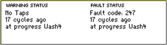
Fault 246 – Bleach Valve Fault
Problem: The Motor Controller module has detected that the Bleach valve is faulty. It determines this by measuring voltages from the valve diagnostic circuit. The most likely cause is that the valve harness has not been connected correctly or the valve is open circuit.
Solution: 1. Check wiring harness to the valve and measure resistance of solenoid.
Fisher and Paykel Washing Machine Service/Fault Code Menu Access
Here are some helpful videos on how to diagnose the problem with your Fisher and Paykel washing machine.
These videos will let you see Fisher and Paykel washing machine fault codes that last occurred on your machine.